While I wait for a few last parts to arrive for my control panel, I’ve
started on wiring the underside of my benchwork. I purchased three 10
position terminal strips off eBay and attached them to the underside of my
bench along one of the support beams. I then connected a power lead from
each track power block to the corresponding terminal connector.
All of the switch machine and turn-table power leads were also wired to a
terminal. The common DC and AC ground leads also attach to terminals on the
strip. Once the control panel is attached to the benchwork, the power and
control leads from it will pass through the large hole to the right of the
terminal strips, connecting to their appropriate terminal on the terminal
strip.
Terminal strips were very helpful in this situation as it gave a common
point where my control panel wiring and layout wiring joined together.
Furthermore, the strips keep everything neat and tidy. I tried to keep the wires as organized as possible. However, since I wired
the layout in stages the final wiring resulted in lots of connection points
along several individual leads. For these connections, I used high quality
male & female connectors, wrapped in electrical tape to prevent loose
connections.
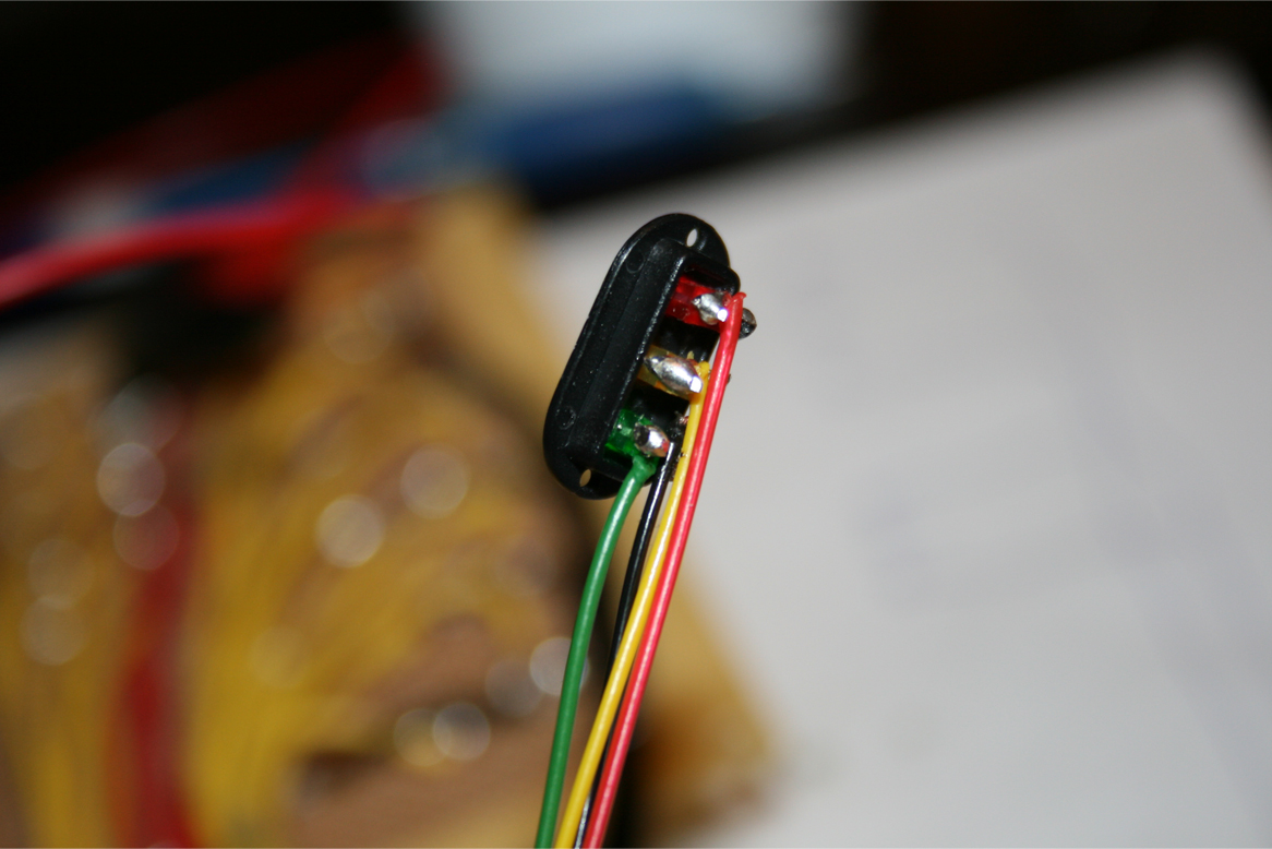
I have also decided to build my own track signals from scratch. I purchased
the small LED lights and black display faces off eBay for a very reasonable
price ($5.00 for all of the LEDs and 8 black display faces). I used super
glue to attach the LEDs to the display faces. I then soldered all the
grounds together and ran one common ground to all 3 LEDs. I then soldered
individual wires to each LED.
These wires will then go to the control panel and their corresponding relay
switch, which will control what LED is lit up depending on the turnout
position. I used standard telephone cable for my leads, which worked
perfectly as there was a black, red, yellow, and green wire which matched
perfectly to the LED light colours. I still need to figure out how I’m going
to construct the rest of the signal structure, but I’ll save that for the
new year.


1 comments
ReplyDeleteCG Board 1st, 2nd, 3rd, 4th, 5th syllabus PDF is announced in online mode. Chhattisgarh SCERT Class 5th English, and Hindi medium Books, Question Bank, learns outcomes and other study materials are download on this page.SCERT CG 5th Class Syllabus For additional particulars on Chhattisgarh Class 5th Text Books, Syllabus, Blueprint, Question Papers, Sample Papers, and Question Bank kindly view the official web.