Wiring Diagrams
Below are a few
wiring diagrams that I have put together that might be useful for others
building a layout for the first time. Since my layout is entirely traditional
DC controlled, the diagrams I have included are all based on DC circuits, even
though some may be integrated or combined with a DCC layout.
The first five
diagrams show how to add more advanced operation and features to your layout
using electrical products from Atlas. The last two diagrams include a master
wiring schematic of my entire layout and control panel, as well as an IC
schematic for my traffic light controller.
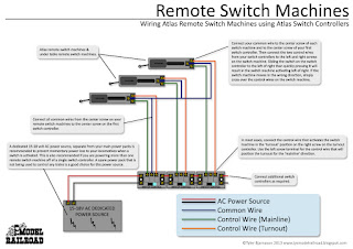
WIRING REMOTE SWITCH MACHINES
How to wire Atlas remote switch machines and Atlas switch controllers.
WIRING A TURNTABE WITH DUAL CABS
How to use dual cab control to power and operate a turntable and turntable motor using an Atlas controller and Atlas selectors.
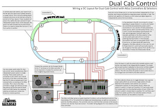
WIRING FOR DUAL CAB CONTROL
How to wire a layout for dual cab control using an Atlas controller and selectors.
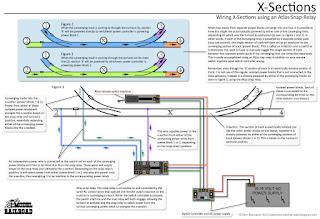
WIRING AN X-SECTION
How to wire an x-section using an Atlas snap relay and existing remote switch machine wiring.
WIRING TRACKSIDE SIGNALS
How to wire trackside signals using an Atlas snap relay and LED lamps to show turnout positions.
MY LAYOUT - MAIN SCHEMATIC
This drawing shows the current main wiring schematic for my model. It includes all electrical components, wire leads, indicator lights, switches, and resistors. This diagram is accurate and is an exact representation of my wiring, both in my control box and on my layout.
TRAFFIC LIGHT CONTROLLER CIRCUIT
This schematic is directly based on Rob Paisley's 20 Output Sequencing Circuit, which I constructed for my own layout's traffic lights. For more information on how this circuit functions and is constructed, please visit Rob's site here.


